
To interpret a floor plan, familiarize yourself with common symbols and shortcuts indicating walls, doors, windows, electrical fixtures, and plumbing components. Walls are shown as parallel lines, while doors appear as gaps with swing arcs. Windows are breaks in walls with a thin line, and electrical items like outlets and switches have specific symbols. Plumbing fixtures are represented by simplified shapes like rectangles and ovals. Mastering these symbols streamlines understanding of layout details—continue exploring to uncover all the essential symbols and shortcuts.
Key Takeaways
- Identify wall types, door swings, and window placements through their standard symbols to understand room layouts.
- Recognize electrical symbols like outlets, switches, and fixtures to interpret the electrical plan.
- Understand plumbing fixture icons such as sinks, toilets, and bathtubs for accurate plumbing layout reading.
- Use symbols for stairs, storage, and structural elements to grasp vertical circulation and space functions.
- Familiarize yourself with common shortcuts and symbols for quick interpretation and efficient reading of floor plans.
Have you ever wondered what those symbols and shortcuts on a floor plan actually mean? Understanding these visual cues is essential for accurately interpreting architectural drawings. Floor plan symbols serve as standardized representations of building components, allowing you to quickly identify structural elements, fixtures, and systems without cluttering the drawing with text. Each symbol is designed to convey specific information efficiently, and recognizing them requires familiarity with common conventions.
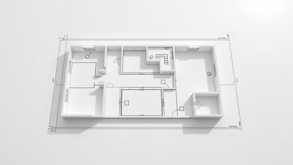
Start with the walls, which are typically depicted as parallel lines, with their thickness indicating the type of wall—interior or exterior. Solid lines represent load-bearing or exterior walls, while dashed or thinner lines often denote non-structural or partition walls. Doors are shown as gaps in walls with an arc indicating the swing direction, revealing how the door opens and closes. Windows are represented by breaks in the wall lines with a thin line across the opening, illustrating the window’s position and size. These symbols allow you to visualize the flow and access within the space, essential for spatial planning and modifications.
Walls are shown as parallel lines; door swings are arcs; windows are breaks with thin lines, revealing layout flow.
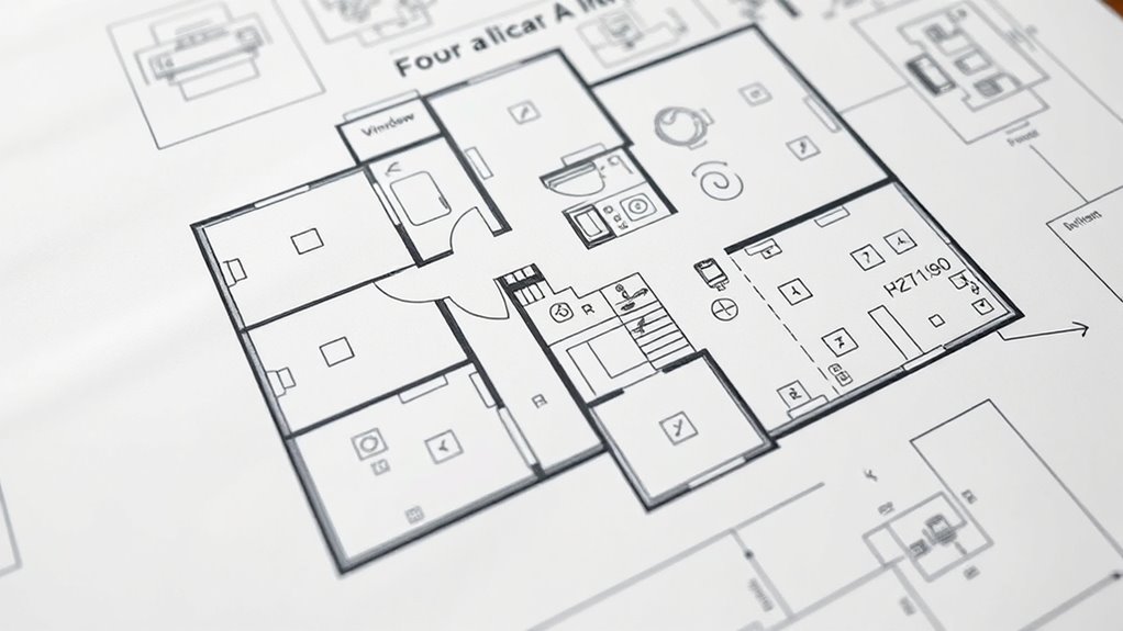
Electrical fixtures are indicated by standardized symbols. Outlets are marked as small circles with lines connecting to the wall, while switches are represented as ‘S’ or a small ‘X’ along the wall line, often with a number indicating the switch’s circuit or control point. Light fixtures are shown as circles with a cross or specific symbols denoting ceiling or wall-mounted lights. Understanding these shortcuts enables you to determine the electrical layout quickly, facilitating installation, renovation, or troubleshooting.
Plumbing fixtures follow a similar pattern. Sinks are often shown as rectangles with a faucet symbol, while toilets are depicted as elongated ovals with a tank outline. Bathtubs and showers are represented by simplified geometrical shapes, with lines indicating plumbing connections. Recognizing these symbols helps you plan plumbing work accurately, ensuring fixtures align with the building’s infrastructure. Additionally, understanding the contrast ratio of fixtures and surfaces can influence the placement and type of plumbing and lighting to optimize the space.
Finally, other symbols include stairs, which are illustrated as a series of lines with an arrow indicating upward or downward movement, and storage or closet spaces, marked by simple rectangles or labeled areas. Each symbol’s clarity and consistency are essential for precise communication among architects, builders, and clients. By mastering these symbols and shortcuts, you’ll develop the ability to read a floor plan quickly and accurately, making informed decisions about design, construction, or renovation projects. Remember, the key lies in recognizing standardized signs and understanding their context within the overall layout.

Height & Time Conversion Vertical Badge ID Card Pocket Reference Guide
Side one converts height into total in and cm and side two converts time into military format
As an affiliate, we earn on qualifying purchases.
As an affiliate, we earn on qualifying purchases.
Frequently Asked Questions
How Do I Interpret Electrical Symbols on a Floor Plan?
You interpret electrical symbols on a floor plan by first identifying standard icons, such as circles for outlets and lines for wiring. Look for labels like “Switch” or “Fixture” to understand their functions. Use the legend or key provided on the plan to decode unfamiliar symbols. Pay attention to line types and arrowheads, which indicate wiring routes and control points, ensuring a clear understanding of the electrical layout.
What Do Different Line Types Indicate on a Blueprint?
Different line types on a blueprint serve specific functions: solid lines depict visible edges and structural elements, dashed lines indicate hidden features or overhead components, and dotted lines show movement paths or future installations. Thick lines emphasize load-bearing walls, while thin lines outline fixtures and details. Using these line types consistently helps you interpret the design accurately, ensuring that construction aligns with intended specifications and facilitating clear communication among project stakeholders.
How Can I Identify Door Swing Directions Quickly?
You can identify door swing directions quickly by examining the door symbol on the plan. The arc shows the swing path; if it opens inward, the arc is inside the room, and if outward, outside. Look for the hinge side, indicated by a thicker line or a specific symbol. This visual cue allows you to determine the swing direction efficiently, ensuring accurate understanding of space flow and clearance.
Are There Standard Symbols for Appliances in Kitchens?
Yes, there are standard symbols for kitchen appliances on floor plans. You’ll see a rectangle with a circle for a stove, a rectangle with a small circle for a microwave, and a square with a line for a dishwasher. Refrigerators are shown as tall rectangles with a dividing line. These symbols help you quickly identify appliance locations, ensuring accurate interpretation of the layout and efficient planning or installation.
How Do I Read Elevation Markers on a Floor Plan?
Ever wondered how elevation markers tell the story of a building’s height? You read them by locating the elevation numbers, usually in feet or meters, next to the marker symbols—like a number with a triangle or circle. The arrows point in the direction of the view, indicating whether the elevation rises or falls. By understanding these symbols and numbers, you grasp the relative height differences across the plan accurately.

Leviton Combo Switch and Receptacle, 109-05225-WSP, White
Fill a one-gang space with a swithc and receptacle
As an affiliate, we earn on qualifying purchases.
As an affiliate, we earn on qualifying purchases.
Conclusion
Mastering floor plan symbols and shortcuts is like learning a new language—each symbol a word, each shortcut a phrase. Once you understand them, you can navigate layouts with confidence, much like reading a map. I once helped a novice quickly interpret a complex blueprint, revealing hidden spaces and design intent. Precision in understanding these symbols guarantees clarity, efficiency, and accuracy—vital for successful project execution. With practice, reading floor plans becomes an intuitive skill, opening the full potential of architectural communication.

48' x 24' Garage or ADU Building Plans – Construction Set with Floor Plan, Elevations, Electrical & Plumbing
Detailed 48' x 24' building plans for garage or ADU
As an affiliate, we earn on qualifying purchases.
As an affiliate, we earn on qualifying purchases.

Rena Chris Architectural Scale Ruler: 12" Imperial Aluminum Alloy Metal Architecture Measuring Tools, Engineering Drafting Construction Drawing Blueprints Triangular Architect Scaling Rulers 12 Inches
12" triangular architect scale designed to facilitate the drafting and measuring of architectural drawings, such as floor plans,…
As an affiliate, we earn on qualifying purchases.
As an affiliate, we earn on qualifying purchases.